Build a Robot That
Plays Soccer
Five clean Python files working together: sense the ball, hold your heading, orbit into position, then push. Every setting lives in one place so tuning takes seconds, not an afternoon.
sense → decide → act (every 10 ms)
Tomo – Testing & Tuning
Prepare both robots for the event, tune the settings file and practice the engineering cycle before the modules.
How the robot plays soccer
What each part of the robot does and the simple decision it makes every 10 ms.
Modular programming
Why we use five separate files and how they connect to each other.
settings.py
One place for all the numbers. Change one value; the whole robot changes.
drive.py
How the code turns a direction and speed into motor commands.
imu.py
A digital compass so the robot always faces the goal after a bump.
sensor_ring.py
Reading where the ball is from the ring of IR sensors around the robot.
main.py
The main loop that ties everything together and makes the robot play.
Wiring Reference
Pin tables for motors, IMU, and the sensor-ring UART.
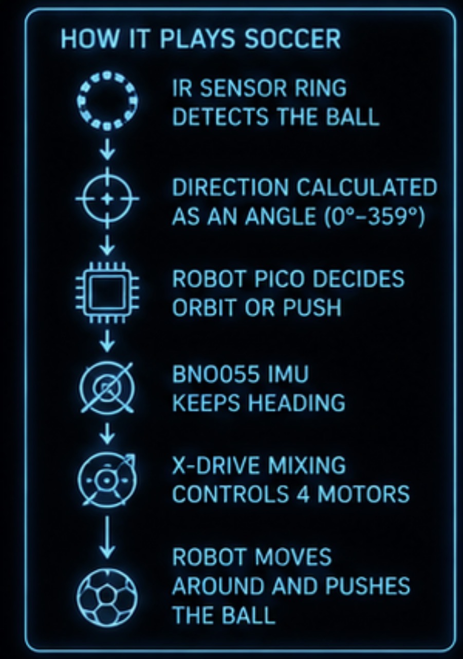
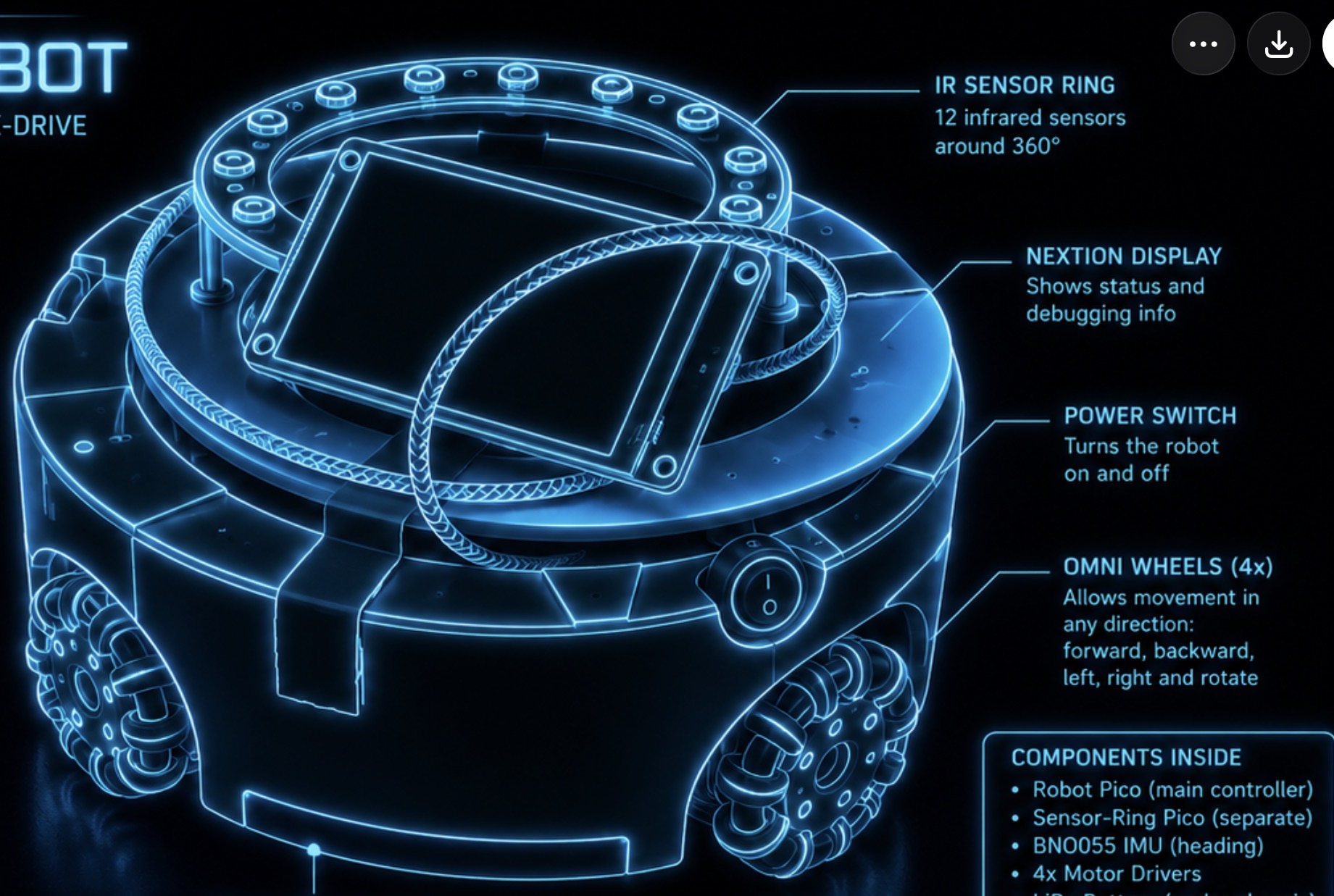
A ring of 12 IR sensors detects the ball and sends its direction as a number (0–359).
BNO055 keeps the robot pointing at the goal even after collisions.
Four wheels at 45° let the robot slide in any direction without turning its body.
Tomo – Testing and Tuning the Soccer Robots
Before you start the coding modules, prepare both robots for the event and practise
adjusting the settings.py file. Use this engineering cycle every time you make a change:
Observe → Change → Save → Test → Evaluate → Improve
🎯 Learning goals
- Safely prepare the soccer robots for the event
- Connect to the Pico using Thonny and stop background programs
- Back up and restore the original
settings.py - Explain how each main behaviour setting affects the robot
- Adjust one constant at a time, test, and evaluate
- Apply successful settings to the second robot
- Pack both robots correctly for transport
Part 1 – Prepare the robots
- Open the robot carefully.
- Remove the old batteries and insert the replacements.
- Check the positive + and negative – markings on each cell.
- Make sure the batteries are sitting securely in the holder.
⚠ Incorrectly fitted batteries can stop the robot from working and could damage the electronics.
- Connect the USB cable to the main Pico inside the robot.
- Connect the other end to the computer.
- Open Thonny and select the Raspberry Pi Pico interpreter.
- Press the red Stop button.
Pressing Stop is essential. The Pico may already be running main.py in the background. Stopping the program lets you safely open, edit and save files.
- In Thonny, open the files stored on the Raspberry Pi Pico.
- Open
settings.pyand read through the values. - Copy the complete contents and save to the computer with a clear name:
original_robot_settings.pyDo this separately for each robot if their settings differ. This backup lets you restore the robot if a change makes things worse.
- Disconnect the USB cable from the computer but leave it plugged into the Pico inside the robot.
- Route the cable so it cannot touch the wheels or moving parts.
- Close the robot.
Leaving the cable inside the robot means you can reconnect quickly without reopening it each time.
Part 2 – Observe the original behaviour
- Place the robot on the soccer mat with clear space around it.
- Turn on the IR ball and start one robot only.
- Move the ball to different positions: directly in front, left, right, beside the robot, behind it, and while moving slowly then quickly.
Watch before changing anything.
- How quickly does it move towards the ball?
- Does it drive straight when the ball is in front?
- Does it circle around the ball when it is beside it?
- Does it orbit too widely or too tightly?
- Does it wobble while holding its heading?
- Does it overshoot the ball?
- Does it stop when the ball is turned off?
- Does it push with enough power?
Record your observations before making changes.
Part 3 – Understand the settings
The constants below have the greatest effect on how the robot behaves. Every value lives in settings.py — change the file, save it to the Pico, and the robot behaves differently.
⚡ Motor power
ORBIT_POWER = 24000Power used while the robot is circling around the ball.
- Higher → orbits faster, may overshoot
- Lower → orbits more accurately, may struggle if too low
Try adjustments of 1 000 – 2 000 at a time.
PUSH_POWER = 32000Power used when the ball is directly in front and the robot drives to push it.
- Higher → accelerates faster, more powerful push, may lose control
- Lower → more controlled approach, may not push effectively
MAX_POWER = 60000An upper limit that protects the motors. Do not change this during normal tuning.
🎱 Ball behaviour
FRONT_WINDOW = 15How close to the front (in degrees) the ball must be before the robot drives straight at it instead of orbiting.
- Larger (e.g. 20) → pushes from a wider angle, less orbiting
- Smaller (e.g. 10) → requires more precise alignment, more orbiting
BALL_TIMEOUT = 500 (milliseconds)How long the robot accepts the last ball reading before deciding the signal is too old. 500 ms = 0.5 seconds.
- Higher → tolerates short signal gaps, may move on stale data
- Lower → stops sooner when ball is lost, may stop too often if the sensor briefly drops
ORBIT_OFFSET = 0.85Controls the size of the orbit path. The robot shifts its target behind the ball by this amount.
- Larger (e.g. 1.00) → wider orbit, stronger position behind ball
- Smaller (e.g. 0.70) → tighter orbit, reaches ball faster but may approach from the side
Adjust in steps of 0.05 – 0.10.
REAR_ZONE = 120Angle beyond which the robot switches to special rear-ball movement. With 120, the rear behaviour starts when the ball is more than 120° from the front.
- Smaller → enters rear behaviour sooner, stronger reaction at rear corners
- Larger → uses normal orbit longer
Adjust by 5° – 10° at a time.
REAR_RIGHT_ANGLE = 100 and REAR_LEFT_ANGLE = 260The escape directions used when the ball is behind the robot. Keep these balanced. A value closer to 90° / 270° is more sideways; further is more backward.
🌟 Heading control
HEADING_KP = 700Proportional gain for heading correction. The equation is:
rotation correction = heading error × HEADING_KPExample: a 10° error with KP 700 gives a correction of 7 000.
- Higher → corrects faster, may cause wobble if too high
- Lower → smoother movement, slower to recover heading
Adjust in steps of 50.
MAX_ROTATION = 18000The maximum turning correction allowed, even if the heading equation gives a larger result.
Example: error 40° × KP 700 = 28 000, but MAX_ROTATION caps it at 18 000.
- Higher → more aggressive recovery, risk of wobble
- Lower → gentler turning, slower recovery
The following control wiring and communication — do not touch them unless fixing a known hardware problem:
RX_PIN  UART_ID  UART_BAUD
IMU_I2C_ID  IMU_SDA_PIN  IMU_SCL_PIN  IMU_FREQUENCY
MOTOR_PINS
Part 4 – Choose your first adjustment
Pick one problem you observed and one setting that is likely to affect it.
| Observed behaviour | Setting | Change |
|---|---|---|
| Orbit too wide | ORBIT_OFFSET | Reduce by 0.05 – 0.10 |
| Orbit too tight | ORBIT_OFFSET | Increase by 0.05 – 0.10 |
| Orbit too fast | ORBIT_POWER | Reduce by 1 000 – 2 000 |
| Orbit too slow | ORBIT_POWER | Increase by 1 000 – 2 000 |
| Robot pushes too slowly | PUSH_POWER | Increase by 1 000 – 2 000 |
| Robot overshoots | PUSH_POWER | Reduce by 1 000 – 2 000 |
| Pushes before lining up | FRONT_WINDOW | Reduce by 5 |
| Takes too long to push | FRONT_WINDOW | Increase by 5 |
| Wobbles while driving | HEADING_KP | Reduce by 50 |
| Heading corrects too slowly | HEADING_KP | Increase by 50 |
| Turns too aggressively | MAX_ROTATION | Reduce by 1 000 – 2 000 |
| Rear movement extreme | Rear angles / REAR_ZONE | Small angle adjustment |
Part 5 – Edit and save the settings file
- Turn the robot off, open it and connect the USB cable to the computer.
- Open Thonny, select the Pico interpreter and press Stop.
- Open
settings.pyand change exactly one constant. - Add a comment recording the original value:
# Original value was 0.85 ORBIT_OFFSET = 0.75 - Save the file to the Pico as
settings.py— notsettings(1).pyornew_settings.py.
- Open the Pico file list in Thonny.
- Delete the existing
settings.pyon the Pico. - Go to File → Save as → Raspberry Pi Pico.
- Save as
settings.pyand confirm it appears in the file list.
Do not delete your computer backup.
Parts 6–8 – Test, record and repeat
- Disconnect from the computer, close the robot, place it on the mat.
- Turn on the ball and start the robot.
- Run the same test movements as before.
- Ask: did the change improve things? Did it create a new problem? Should the value go higher, lower, or back to the original?
| Test | Setting changed | Old value | New value | What happened? | Keep? |
|---|---|---|---|---|---|
| 1 | ORBIT_OFFSET | 0.85 | 0.75 | Tighter orbit, reached ball faster | Keep |
| 2 | ORBIT_POWER | 24000 | 26000 | Overshot the ball | Revert |
| 3 | HEADING_KP | 700 | 650 | Smoother movement | Keep |
Record every change — even unsuccessful ones give you useful information.
Observe → Choose setting → Adjust → Save → Test → Evaluate → Keep or Revert
Do not guess randomly. Every change should have a reason based on what you observed.
- Open the original backup saved on the computer.
- Find the original value and change the setting back.
- Save
settings.pyto the Pico and test the robot to confirm original behaviour has returned.
Part 10 – Test both robots together
- Decide which changes clearly improved robot 1.
- Apply the successful settings to robot 2.
- Test robot 2 alone first, then test both together.
Watch for: robots blocking each other, both approaching from the same side, one losing the ball, or one robot being noticeably faster. The same settings may not produce exactly the same result on both robots because of slight differences in motors, wheels and batteries.
Part 11 – Final event preparation
- Turn both robots off.
- Check batteries are secure and shells are closed correctly.
- Check no wires are hanging near the wheels.
- Pack each robot safely in its transport tube.
- Include USB cables, chargers and spare batteries.
- Give the packed robots to Mrs Rumminie to take to the event.
Part 12 – Code understanding practice
Use any remaining time to:
- Read through the learning modules and watch the instruction videos
- Review each Python file and identify the purpose of each function
- Practise explaining how the robot finds and follows the IR ball
- Complete the calculations below using a calculator
Heading error:
heading error = target heading − current heading
(adjusted to remain between −180° and +180°)
Rotation correction:
rotation correction = heading error × HEADING_KP

Example: −12° × 700 = −8 400
(negative = robot rotates the other way)
Maximum rotation limit:
If: 35° × 700 = 24 500
But: MAX_ROTATION = 18 000
Result: robot uses 18 000, not 24 500
Millisecond conversions:
500 ms = 0.5 s | 400 ms = 0.4 s | 250 ms = 0.25 sYou may use an AI assistant (e.g. ChatGPT) to help explain code or calculations. Useful questions:
- "Explain proportional control in simple terms."
- "Why does increasing HEADING_KP make the robot turn more strongly?"
- "Help me understand this Python function one line at a time."
- "Give me another example of calculating heading correction."
Always read the explanation and complete the calculation yourself using a calculator — do not just ask for the answer.
✅ Completion checklist
- ☐ Batteries replaced and directions checked
- ☐ Main Pico connected to Thonny and background program stopped
- ☐ Original
settings.pybacked up on the computer - ☐ Robot tested using its original settings
- ☐ Original behaviour recorded
- ☐ Main behaviour constants reviewed
- ☐ At least three controlled setting changes tested
- ☐ Results recorded in the test table
- ☐ Unsuccessful changes reverted
- ☐ Successful settings tested on the second robot
- ☐ Both robots tested together
- ☐ Robots turned off, checked and packed in transport tubes
- ☐ Robots given to Mrs Rumminie
- ☐ Remaining modules read and videos watched
- ☐ Heading calculations completed with a calculator
💬 Final reflection
- Which setting had the greatest effect on the robot’s movement?
- What was the best change you made?
- Which change made the robot worse?
- How did you know whether a test was successful?
- Why is it important to change only one setting at a time?
- Why should you keep a copy of the original settings?
- How does
HEADING_KPaffect the robot’s turning? - How does
ORBIT_OFFSETaffect the path around the ball? - Which settings would you adjust if the robot was orbiting too widely?
- What would you test next if you had more time?
📌 Original settings reference
If you are unsure what a setting was before you changed it, use this table to find the original value.
Copy the value back into settings.py, save the file to the Pico, and the robot will behave as it did at the start.
| Constant | Original value | What it controls |
|---|---|---|
ORBIT_POWER | 24000 | Power while circling the ball |
PUSH_POWER | 32000 | Power when driving straight at the ball |
MAX_POWER | 60000 | Upper limit on any motor command |
| Constant | Original value | What it controls |
|---|---|---|
FRONT_WINDOW | 15 | Angle range (degrees) where ball counts as “in front” |
BALL_TIMEOUT | 500 | Milliseconds before a stale ball reading is rejected |
ORBIT_OFFSET | 0.85 | Size of the behind-ball shift in the orbit path |
REAR_ZONE | 120 | Angle past which the rear-ball escape movement triggers |
REAR_RIGHT_ANGLE | 100 | Escape direction when the ball is behind-left |
REAR_LEFT_ANGLE | 260 | Escape direction when the ball is behind-right |
| Constant | Original value | What it controls |
|---|---|---|
HEADING_KP | 700 | How strongly the robot turns to correct its heading |
MAX_ROTATION | 18000 | Maximum turning correction applied at any time |
ROTATION_SIGN | 1 | Turn direction for heading correction (1 or −1 only) |
| Constant | Original value | What it controls |
|---|---|---|
RX_PIN | 5 | GP5 — receives ball angle from sensor ring |
UART_ID | 1 | UART peripheral used for sensor ring |
UART_BAUD | 115200 | Communication speed with the sensor ring |
IMU_I2C_ID | 0 | I²C peripheral used for the compass chip |
IMU_SDA_PIN | 0 | GP0 — I²C data line to BNO055 |
IMU_SCL_PIN | 1 | GP1 — I²C clock line to BNO055 |
IMU_FREQUENCY | 10000 | I²C bus speed (10 kHz) |
Grey values indicate settings that should not be changed during normal tuning. Only adjust these if you are fixing a known wiring or communication problem.
How the robot plays soccer
Before you write any code, it helps to picture the whole robot and understand the single decision it makes over and over again.
🎯 What you’ll understand
- What each hardware piece on the robot does
- How the robot decides whether to push or go around the ball
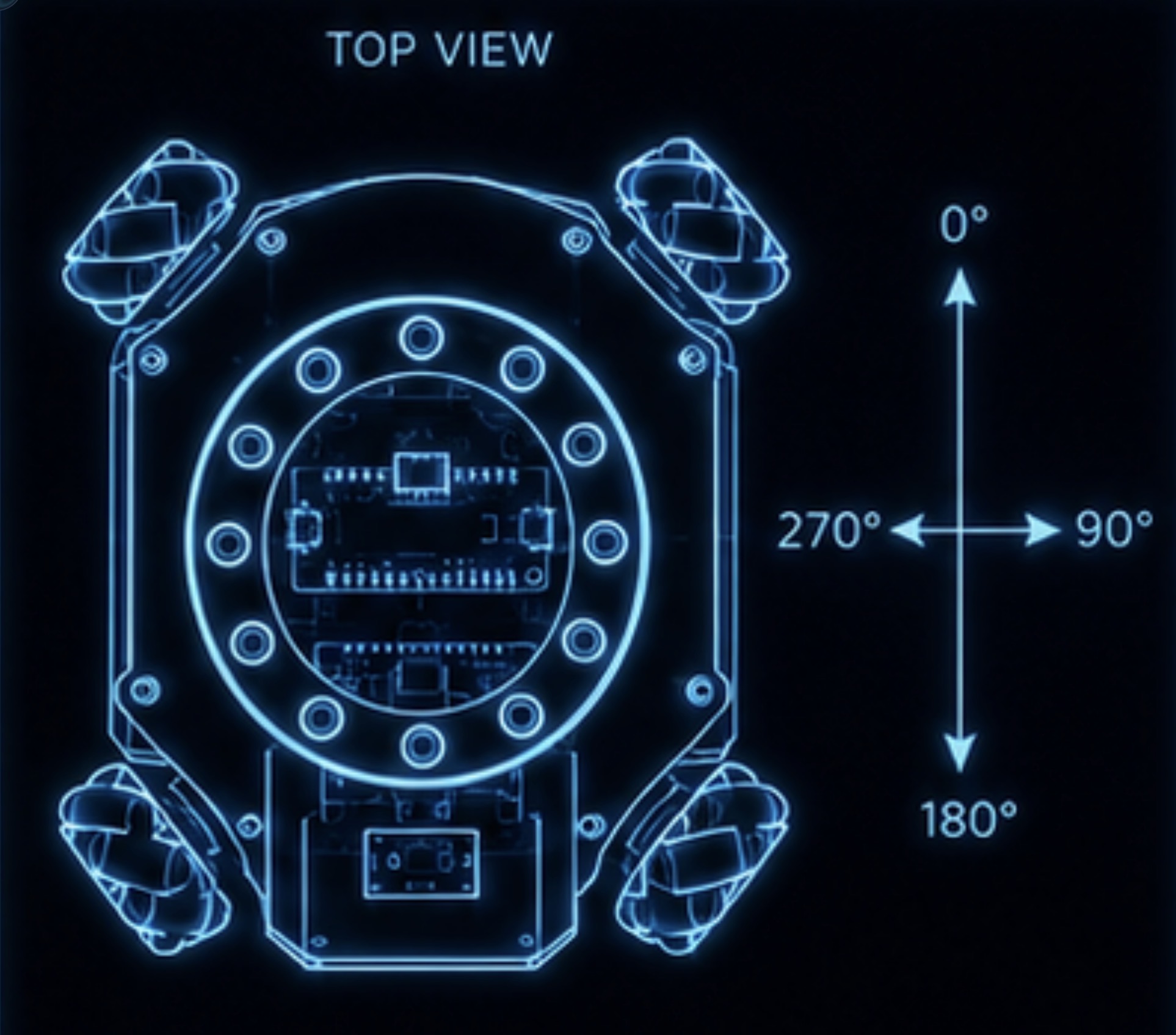
- What the angle numbers (0–359) mean
What the robot does — in plain words
Imagine you are watching the ball. You decide: is the ball right in front of me? If yes — run forward and push it. If no — run around to get behind it, then push.
The robot does exactly this, but 100 times per second. It reads where the ball is, makes that one decision, and drives its motors. That's it.
Three pieces of hardware make this possible: a ring of sensors to find the ball, a compass chip to know which way the robot is facing, and four motors to move in any direction.
Under the hood: the control loop
The Pico runs an infinite while True: loop with a 10 ms sleep at the end — that's 100 cycles per second. Each cycle: read the sensor ring (ball angle 0–359°), read the IMU (compass heading), calculate a rotation correction, then either push or orbit.
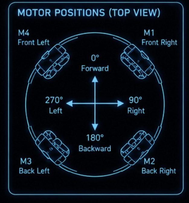
The ball angle uses a clockwise compass centred on the robot: 0° = straight ahead, 90° = right, 180° = behind, 270° = left. The push/orbit decision uses wrap_180() to convert 0–359 into –180 to +180, making left/right comparisons easy.
The ball is behind you — what do you do?
If the ball is directly behind, you can't just drive backwards into it because then the goal would be behind the ball and you'd score an own goal. Instead the robot drives around to a position behind the ball, then pushes.
The program calls this circling movement orbiting. Once the ball is directly in front (within 15°), the robot switches to pushing.
Orbit vs push decision
Every loop, signed_angle = wrap_180(angle) converts the ball angle to a signed value. If abs(signed_angle) <= FRONT_WINDOW (15°) → call drive_angle(0, PUSH_POWER, rotation). Otherwise → call drive_angle(orbit_angle(angle), ORBIT_POWER, rotation).
The orbit_angle() function calculates a drive direction that naturally swings the robot around and behind the ball. The IMU rotation correction runs on every cycle regardless of push or orbit mode.
🔑 Python Symbol Key — click to expand
| Symbol | What it means |
|---|---|
| 0°, 90°, 180°, 270° | Compass directions from the robot's front — clockwise |
| abs(x) | Absolute value: strips the minus sign. abs(-12) = 12 |
| <= | Less than or equal to |
Modular programming
Instead of one enormous file, the soccer program is split into five smaller files. Each file has one clear job.
🎯 What you’ll understand
- Why splitting code into files makes it easier to work with
- What each of the five files is responsible for
- How the files talk to each other
- Which file to open when you want to tune the robot
Why five files instead of one?
Think of it like a restaurant kitchen. One chef handles sauces, another handles grilling, another handles desserts. They all work together, but each only needs to know their own job.
Our five files work the same way. If the robot is steering wrong you open settings.py. If a motor spins the wrong way you open drive.py. You never have to read the whole program — just the part that needs fixing.
The most important file for tuning is settings.py. Every speed, power, and threshold lives there. You will rarely need to edit the others.
The five files and what they do
| File | Job | Imports from |
|---|---|---|
| settings.py | All tunable constants | nothing |
| drive.py | Motor control, drive_angle(), stop() | settings |
| imu.py | Compass heading from BNO055 | settings |
| sensor_ring.py | Ball angle from the IR sensor ring | settings |
| main.py | Startup, control loop, decisions | all four above |
How the files share information — the simple version
When one file needs a value from another, it imports it. Think of it like one teammate shouting a number to another. drive.py calls over to settings.py: "Hey, what's MAX_POWER?" and settings answers.
Every time you change a number in settings.py, every other file automatically gets the new value the next time the program runs. You only change one file to tune the whole robot.
How imports work in MicroPython
from settings import MAX_POWER, MOTOR_PINS tells Python: look for a file called settings.py in the same folder and bring just those two names into this file's namespace. All five files must be uploaded to the Pico together.
Upload order: upload the four supporting files first, then main.py last. The Pico automatically runs whatever file is named main.py on boot.
🔑 Python Symbol Key — click to expand
| Symbol | What it means |
|---|---|
| import x | Bring the whole file x.py into this file |
| from x import y | Bring only the name y from file x.py |
| . | Dot — access something that belongs to an object: ring.read() |
settings.py
Every number the robot uses is stored here. If you want the robot to move faster, push harder, or react sooner — this is the only file you touch.
🎯 What you’ll understand
- What every number in the file controls
- Which numbers to change first when tuning
- Why pin numbers are stored here instead of scattered through other files
What is settings.py?
It's a list of named numbers. Every number that controls the robot's behaviour is given a clear name here. Instead of hiding 32000 somewhere in the motor code, we write PUSH_POWER = 32000 so anyone can see what it does.
The six groups cover: the wire between the two Picos, how fast the motors spin, how the robot chases the ball, how it corrects its heading, where the compass chip is wired, and where the motors are wired.
The six constant groups
UART: RX_PIN=5 (GP5 receives ball angles), UART_ID=1 (UART peripheral 1), UART_BAUD=115200 (must match the sensor ring).
Motor power: ORBIT_POWER=24000, PUSH_POWER=32000, MAX_POWER=60000 — PWM duty cycle values (0–65535 range).
Ball behaviour: FRONT_WINDOW=15 (push when ball is within ±15°), BALL_TIMEOUT=500 (stop after 500 ms with no data).
Heading control: HEADING_KP=700 (P-gain), MAX_ROTATION=18000 (cap on correction), ROTATION_SIGN=1 (flip to −1 if correction goes the wrong way).
IMU wiring: IMU_I2C_ID=0, IMU_SDA_PIN=0, IMU_SCL_PIN=1, IMU_FREQUENCY=100000.
Motor pins: list of four (IN1, IN2) pin pairs — one per motor.
What is a constant?
A constant is a named value that is set once and never changed while the program runs. In Python, programmers write constants in ALL_CAPS so they stand out from ordinary variables.
For example, instead of hiding the number 32000 deep inside the motor code, we write:
PUSH_POWER = 32000
Now every part of the program can use PUSH_POWER. If you want to change the push speed, you change it once here in settings.py — not in five different places across five files. This is the main reason the settings file exists.
Python does not enforce constants — nothing stops you writing PUSH_POWER = 99 later. The ALL_CAPS name is a convention that tells other programmers (and your future self): treat this as fixed.
# Sensor-ring UART
RX_PIN = 5
UART_ID = 1
UART_BAUD = 115200

# Motor power
ORBIT_POWER = 24000
PUSH_POWER = 32000
MAX_POWER = 60000

# Ball behaviour
FRONT_WINDOW = 15
BALL_TIMEOUT = 500
ORBIT_OFFSET = 0.85
REAR_RIGHT_ANGLE = 100
REAR_LEFT_ANGLE = 260
REAR_ZONE = 120

# Heading control
HEADING_KP = 700
MAX_ROTATION = 18000
ROTATION_SIGN = 1

# IMU wiring
IMU_I2C_ID = 0
IMU_SDA_PIN = 0
IMU_SCL_PIN = 1
IMU_FREQUENCY = 100000

# Motor wiring
MOTOR_PINS = [
    (11, 10),
    (13, 12),
    (15, 14),
    (18, 19)
]
💡 Try it
Upload settings.py to the Pico. In the Thonny REPL type:
from settings import PUSH_POWER; print(PUSH_POWER)
You should see 32000. Change the value, upload again, and check it updated.
🔑 Python Symbol Key — click to expand
| Symbol | What it means |
|---|---|
| = | Assignment — give a name to a value: PUSH_POWER = 32000 |
| # | Comment — Python ignores this line, it's just a note for humans |
| [ ] | List — a collection of items in order |
| (11, 10) | Tuple — a fixed pair of values, used here for two pin numbers |
drive.py
This file gives the robot legs. You tell it a direction and a speed; it works out how to spin each of the four wheels.
🎯 What you’ll understand
- How two wires control one motor
- How the robot moves in any direction using four wheels
- How speed is kept safe so no motor gets overloaded
How one motor is controlled
Each motor is connected to a small driver chip with two input wires. To spin the motor one way, put power on wire 1 and zero on wire 2. To spin it the other way, swap them. To stop, put zero on both.
In the code, positive numbers spin the motor one way, negative numbers spin it the other way, and zero stops it. The Motor class handles all of that automatically.
How four wheels move in any direction
Imagine you want to slide to the right without rotating your body. You can't do that with normal wheels — but omni wheels can, because each wheel can also roll sideways.
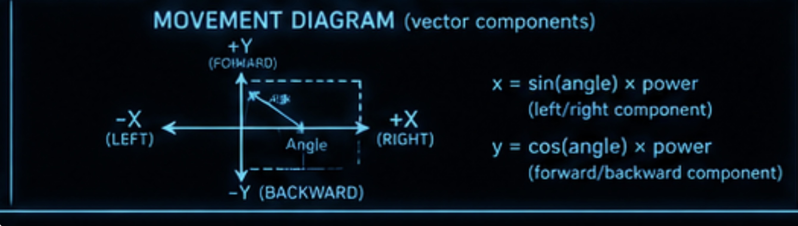
The trick is maths: to move at any angle, we split the movement into a left/right part (x) and a forward/backward part (y). Each wheel gets a combination of those two parts. The robot ends up sliding in exactly the right direction.
Under the hood: PWM and the Motor class
PWM (Pulse Width Modulation) is a way to control power by switching a pin on and off very fast. A duty cycle of 32000 out of 65535 means the pin is on roughly half the time — about half power. The Pico runs PWM at 1000 Hz (1000 cycles per second).
The Motor class wraps two PWM objects (pin1 and pin2). run(speed) clamps speed to ±MAX_POWER, then applies the positive/negative/zero logic to set the two duty cycles.
The mixing equations and speed normalisation
Each wheel sits at 45° to the body. The four-motor mixing formula is:
M1 (front-right): −y + x + rot
M2 (back-right): −y − x + rot
M3 (back-left): +y − x + rot
M4 (front-left): +y + x + rot
After calculating the four speeds, the code finds the largest. If it exceeds MAX_POWER, all four speeds are scaled down by the same factor. This keeps the direction accurate — you never saturate one motor and distort the movement.
What is a class?
A class is a template for creating objects. class Motor: describes what every motor object can do — it can be set up with two pins, run at a speed, and stop. The template is written once, then used four times to create four separate motor objects.
Think of a class like a biscuit cutter: the cutter is the class, each biscuit is an object. Every biscuit has the same shape, but each one is its own separate thing.
In this file the four motors are created all at once using a list:
motors = [Motor(pin1, pin2) for pin1, pin2 in MOTOR_PINS]
This reads the four pin pairs from settings.py and creates one Motor object for each pair, giving a list of four independent motor objects.
What is self?
self means “this particular object”. When a Motor object is created, Python runs __init__(self, pin1, pin2). At that moment, self refers to the new motor being set up.
self.pin1 = PWM(Pin(pin1)) stores the PWM output inside that specific motor object. Later, when run() is called on motor 1, it uses self.pin1 — which belongs to motor 1, not motor 2 or motor 3.
Without self, all four motors would try to share the same variable. With self, each motor keeps its own private copy of its pins. self is always the first parameter in any method inside a class, and Python fills it in automatically — you never pass it yourself.
from machine import Pin, PWM
import math
from settings import MAX_POWER, MOTOR_PINS


class Motor:
    def __init__(self, pin1, pin2):
        self.pin1 = PWM(Pin(pin1))
        self.pin2 = PWM(Pin(pin2))
        self.pin1.freq(1000)
        self.pin2.freq(1000)

    def run(self, speed):
        speed = int(max(-MAX_POWER, min(MAX_POWER, speed)))

        if speed > 0:
            self.pin1.duty_u16(speed)
            self.pin2.duty_u16(0)
        elif speed < 0:
            self.pin1.duty_u16(0)
            self.pin2.duty_u16(-speed)
        else:
            self.pin1.duty_u16(0)
            self.pin2.duty_u16(0)


motors = [Motor(pin1, pin2) for pin1, pin2 in MOTOR_PINS]


def drive(x, y, rotation):
    speeds = [
        -y + x + rotation,
        -y - x + rotation,
         y - x + rotation,
         y + x + rotation
    ]

    largest = max(max(abs(speed) for speed in speeds), 1)

    if largest > MAX_POWER:
        scale = MAX_POWER / largest
        speeds = [speed * scale for speed in speeds]

    for motor, speed in zip(motors, speeds):
        motor.run(speed)


def drive_angle(angle, power, rotation=0):
    angle_rad = math.radians(angle)
    x = math.sin(angle_rad) * power
    y = math.cos(angle_rad) * power
    drive(x, y, rotation)


def stop():
    drive(0, 0, 0)
💡 Try it
Upload all five files. In the REPL:
from drive import drive_angle, stop
drive_angle(0, 20000) — should move forward.
drive_angle(90, 20000) — should strafe right.
stop() — stops all motors.
🔑 Python Symbol Key — click to expand
| Symbol | What it means |
|---|---|
| + − * / | Arithmetic: add, subtract, multiply, divide |
| int(x) | Round x down to a whole number |
| max(a,b) / min(a,b) | Return the larger / smaller of two values |
| abs(x) | Absolute value — removes the minus sign: abs(−5000) → 5000 |
| math.sin(r) / math.cos(r) | Trigonometry — input must be in radians (use math.radians() first) |
| for x, y in pairs: | Loop — run the indented block once for each (x, y) pair in the list |
| zip(a, b) | Pair up two lists element by element |
imu.py
This file talks to the BNO055 compass chip and gives the robot one number every loop: which direction it is currently facing.
🎯 What you’ll understand
- What the IMU does and why the robot needs it
- How two wires carry information between the Pico and the chip
- How the heading number is read and turned into degrees
Why the robot needs a compass
Every time the robot bumps another robot, it gets rotated. Without a compass, it would keep driving in the wrong direction. The BNO055 chip constantly measures which way the robot is pointing.
At startup, the program records the direction the robot is facing as the target heading. If the robot rotates during a game, the loop detects the difference and gently steers it back. This is called heading hold.
If the compass chip is not connected at startup, the program stops immediately and waits. You must fix the wiring before it will run.
What is I²C?
I²C (pronounced “eye-squared-see”) is a system that lets the Pico talk to electronic chips using just two wires:
- SDA — Serial Data. Carries the actual data back and forth.
- SCL — Serial Clock. Ticks like a metronome to keep sender and receiver in sync.
Many chips can share the same two wires at the same time, because every chip has its own unique address — a number that works like a house number. When the Pico wants to read the compass, it calls out the BNO055’s address (0x28 or 0x29) on the wire. Only that chip responds; all others ignore the message.
On this robot: SDA → GP0, SCL → GP1. The Pico runs I²C at 100 kHz (100,000 clock ticks per second), which is standard speed for most sensor chips.
How the chip is wired
The BNO055 uses two wires to talk to the Pico: one carries data back and forth (SDA, connected to GP0), and one ticks like a clock to keep the communication in sync (SCL, connected to GP1). This system is called I²C.
When the code starts, it scans the wire to find which chip is connected (checking addresses 0x28 and 0x29). Once found, it wakes the chip up with a series of setup commands.
Hardware I²C setup
I2C(0, sda=Pin(0), scl=Pin(1), freq=100000) creates a hardware I²C connection using peripheral 0 on the Pico at 100 kHz (standard speed). i2c.scan() returns a list of all device addresses on the bus — we check for 0x28 first, then 0x29.
The constructor writes to three BNO055 registers: 0x3D←0x00 (config mode), 0x3E←0x00 (normal power), 0x3F←0x00 (default axis map), then 0x3D←0x0C (NDOF fusion mode). Small sleep_ms() delays let the chip transition between modes.
Reading the heading value
Register 0x1A holds the heading as two bytes. readfrom_mem(address, 0x1A, 2) reads both at once. data[0] | (data[1] << 8) stitches them into a 16-bit integer — shift the high byte left 8 places then OR it with the low byte.
The BNO055 stores heading in units of 1/16°, so we divide by 16.0 to get degrees. A result of 1440 from the sensor means 1440 ÷ 16 = 90°.
from machine import Pin, I2C
import time
from settings import IMU_I2C_ID, IMU_SDA_PIN, IMU_SCL_PIN, IMU_FREQUENCY


class BNO055:
    def __init__(self, i2c, address):
        self.i2c = i2c
        self.address = address
        self.write(0x3D, 0x00)
        time.sleep_ms(30)
        self.write(0x3E, 0x00)
        self.write(0x3F, 0x00)
        time.sleep_ms(10)
        self.write(0x3D, 0x0C)
        time.sleep_ms(30)

    def write(self, register, value):
        self.i2c.writeto_mem(self.address, register, bytes([value]))

    def heading(self):
        data = self.i2c.readfrom_mem(self.address, 0x1A, 2)
        raw_heading = data[0] | (data[1] << 8)
        return raw_heading / 16.0


def initialise_imu():
    i2c = I2C(
        IMU_I2C_ID,
        sda=Pin(IMU_SDA_PIN),
        scl=Pin(IMU_SCL_PIN),
        freq=IMU_FREQUENCY
    )

    devices = i2c.scan()

    if 0x28 in devices:
        return BNO055(i2c, 0x28)
    if 0x29 in devices:
        return BNO055(i2c, 0x29)

    return None
💡 Try it
Upload all five files. In the REPL:
from imu import initialise_imu
imu = initialise_imu(); print(imu)
Should print a BNO055 object (not None).
print(imu.heading()) — rotate the robot and run again.
🔑 Python Symbol Key — click to expand
| Symbol | What it means |
|---|---|
| 0x28 / 0x3D | Hexadecimal number — 0x prefix means base-16. 0x28 = 40 in normal numbers |
| data[0] | Index — get the first item from a list or bytes object |
| data[1] << 8 | Left bit-shift — multiply data[1] by 256 (shift 8 binary places left) |
| data[0] | (data[1] << 8) | Bitwise OR — combine two bytes into one 16-bit number |
| / 16.0 | Divide by 16.0 — converts the sensor's 1/16° units to degrees |
| if 0x28 in devices: | Check whether 0x28 appears anywhere in the list |
| return None | Return the special empty value — signals 'not found' |
sensor_ring.py
A separate Pico reads 12 IR sensors arranged in a circle and continuously sends the ball direction as a number over a single wire. This file receives and decodes that number.
🎯 What you’ll understand
- How two Picos share data over a wire
- Why we collect data in a buffer before reading it
- How the robot detects that the ball has gone missing
What is UART?
UART (Universal Asynchronous Receiver Transmitter) is a simple way to send text down a wire, one character at a time. It works like a very fast typewriter — each character is sent as a pattern of electrical pulses, and the receiver reassembles the characters into readable data.
The sensor-ring Pico sends the ball angle as plain text: it types the number 143 and then presses “Enter” (a newline character). The robot Pico reads those characters and converts them back into the number 143.
“Asynchronous” means the two Picos do not share a clock wire. Instead, they agree in advance on the baud rate (115 200 bits per second). As long as both sides use exactly the same speed, every bit arrives correctly. If you accidentally set different baud rates on the two Picos, the data will come out as garbage.
UART only needs one data wire in each direction. For this robot, only the sensor ring’s TX wire is used — data flows one way (sensor ring → robot Pico). The RX direction is left unused.
Two Picos talking over one wire
The sensor-ring Pico constantly sends the ball's direction as a number, for example 143, followed by a newline character (like pressing Enter). It does this over a single wire connected to GP5 on the robot Pico.
The robot Pico receives the number and stores it. Every loop it asks: "What is the latest ball angle?" and uses that to decide what to do.
If nothing has arrived for more than 500 ms, the robot assumes the ball is gone (or the wire fell out) and stops. This is the fail-safe.
What does "buffer" mean?
Data arrives at any moment — the robot Pico is busy doing other things at the same time. A buffer is like a waiting room: bytes queue up there until the program is ready to read them.
We keep collecting bytes until we see a newline character. That tells us a complete number has arrived. We read the number, remove it from the buffer, and wait for the next one.
UART streaming and buffering
UART sends one byte at a time at 115200 baud. uart.any() returns how many bytes are waiting — we only call uart.read() when there is something, because reading an empty UART returns None which would crash buffer += None.
We split the buffer on b"\n" (newline byte). Each split gives us a complete line. int(line.strip()) converts the bytes to an integer. The try/except ValueError silently drops any garbled data.
The age() method and the fail-safe
self.last_ball_time = time.ticks_ms() records when the last valid angle arrived. age() returns time.ticks_diff(now, last_ball_time) — the number of milliseconds since then. ticks_diff() handles the 32-bit timer rollover correctly.
In main.py, sensor_ring.age() > BALL_TIMEOUT (500 ms) triggers stop(). The ball angle stays at the last valid value even after the ball disappears — the age is what triggers the stop, not the angle becoming None.
from machine import Pin, UART
import time
from settings import RX_PIN, UART_ID, UART_BAUD


class SensorRing:
    def __init__(self):
        self.uart = UART(UART_ID, baudrate=UART_BAUD, rx=Pin(RX_PIN))
        self.buffer = b""
        self.ball_angle = None
        self.last_ball_time = 0

    def read(self):
        if self.uart.any():
            new_data = self.uart.read()
            if new_data:
                self.buffer += new_data

        while b"\n" in self.buffer:
            line, self.buffer = self.buffer.split(b"\n", 1)

            try:
                value = int(line.strip())
                if 0 <= value < 360:
                    self.ball_angle = value
                    self.last_ball_time = time.ticks_ms()
            except ValueError:
                pass

        return self.ball_angle

    def age(self):
        return time.ticks_diff(time.ticks_ms(), self.last_ball_time)
💡 Try it
With the sensor ring connected (UART TX → GP5 + shared GND), upload all five files.
In the REPL:
from sensor_ring import SensorRing
ring = SensorRing()
import time; time.sleep_ms(500); print(ring.read())
Move the ball around. The number should update. None means no data — check wiring.
🔑 Python Symbol Key — click to expand
| Symbol | What it means |
|---|---|
| b"" | Bytes literal — raw bytes, not a text string |
| += | Add and reassign: buffer += data means buffer = buffer + data |
| b"\\n" in self.buffer | Check whether a newline byte exists in the buffer |
| .split(b"\\n", 1) | Split the buffer at the first newline — returns [before, after] |
| try: ... except ValueError: | If the code inside try fails with a ValueError, run the except block instead |
| pass | Do nothing — required when a block needs a statement but no action is needed |
| time.ticks_diff(a, b) | Safe elapsed time in milliseconds — handles timer rollover correctly |
main.py
This is the brain. It starts everything up, checks the hardware is working, then runs the sense → decide → act loop forever.
🎯 What you’ll understand
- What happens in the 5 seconds after the robot turns on
- How the main loop makes decisions every 10 ms
- How the robot self-corrects its heading using the compass
What happens when the robot turns on
The program waits 3 seconds. This gives you time to set the robot down and let go. It also gives the compass chip time to power up properly.
Next it checks the compass chip is connected. If the chip is not found (wiring problem), the robot stops immediately and waits forever. It will not play soccer without a working compass.
After another 2-second wait for the compass to settle, it reads the heading and saves it as the target heading — the direction the robot should always be pointing. From this moment the main loop starts.
The main loop — what happens every 10 ms
1. Read the ball angle from the sensor ring.
2. Read the compass to see if the robot has rotated.
3. Calculate a correction: if the robot is rotated left, the correction steers it right, and vice versa.
4. Decide: push or orbit? Is the ball within 15° of straight ahead? Push. Otherwise orbit.
5. Drive — send the direction, power, and rotation correction to drive.py.
6. Wait 10 ms and repeat. If anything crashes, stop for 100 ms then continue.
wrap_180() — converting the angle
Ball angles are 0–359°. To easily check "is the ball to the left or right?" we convert to −180 to +180: (angle + 180) % 360 − 180. Negative = left, positive = right.
Example: 270° → (270+180) % 360 − 180 = 450 % 360 − 180 = 90 − 180 = −90. The ball is 90° to the left.
orbit_angle() — getting behind the ball
If the ball is far behind (|signed_angle| > REAR_ZONE = 120°), the robot drives to a fixed angle to swing around quickly. Otherwise it calculates a virtual target: offset the ball position backward by ORBIT_OFFSET (0.85 units), then drive toward that point.
This naturally swings the robot in a wide arc around the ball and deposits it behind it — ready to push.
The heading correction — proportional control
heading_error = wrap_180(target_heading − current_heading) gives the signed angle difference. Multiply by HEADING_KP = 700 to get a rotation value. Clamp it to ±MAX_ROTATION = 18000 so it never overpowers the drive.
This is a P-controller (proportional controller): the bigger the error, the bigger the correction. If the correction direction is wrong, set ROTATION_SIGN = −1 in settings.py.
import math
import time

from drive import drive_angle, stop
from imu import initialise_imu
from sensor_ring import SensorRing
from settings import (
    ORBIT_POWER,
    PUSH_POWER,
    FRONT_WINDOW,
    BALL_TIMEOUT,
    HEADING_KP,
    MAX_ROTATION,
    ROTATION_SIGN,
    ORBIT_OFFSET,
    REAR_RIGHT_ANGLE,
    REAR_LEFT_ANGLE,
    REAR_ZONE
)


def wrap_180(angle):
    return (angle + 180) % 360 - 180


def orbit_angle(ball_angle):
    signed_angle = wrap_180(ball_angle)

    if signed_angle > REAR_ZONE:
        return REAR_LEFT_ANGLE

    if signed_angle < -REAR_ZONE:
        return REAR_RIGHT_ANGLE

    ball_rad = math.radians(ball_angle)
    ball_x = math.sin(ball_rad)
    ball_y = math.cos(ball_rad)

    target_x = ball_x
    target_y = ball_y - ORBIT_OFFSET

    return math.degrees(math.atan2(target_x, target_y)) % 360


time.sleep(3)

sensor_ring = SensorRing()
imu = initialise_imu()

if imu is None:
    stop()
    while True:
        time.sleep(1)

time.sleep(2)
target_heading = imu.heading()

while True:
    try:
        angle = sensor_ring.read()
        current_heading = imu.heading()

        heading_error = wrap_180(target_heading - current_heading)

        rotation = heading_error * HEADING_KP * ROTATION_SIGN
        rotation = max(-MAX_ROTATION, min(MAX_ROTATION, rotation))

        if angle is None or sensor_ring.age() > BALL_TIMEOUT:
            stop()
        else:
            signed_angle = wrap_180(angle)

            if abs(signed_angle) <= FRONT_WINDOW:
                drive_angle(0, PUSH_POWER, rotation)
            else:
                drive_angle(orbit_angle(angle), ORBIT_POWER, rotation)

        time.sleep_ms(10)

    except Exception:
        stop()
        time.sleep_ms(100)
💡 Final test checklist
- Robot waits 3 seconds at boot then initialises — no movement during this window.
- If IMU wiring is wrong: robot stops and never enters the loop. Fix SDA/SCL.
- Ball in front: robot drives straight forward (push mode).
- Ball to the side or behind: robot circles around (orbit mode).
- Remove ball from ring: robot stops within 500 ms (fail-safe).
- Rotate robot by hand: it steers back to the original heading (heading hold).
- Heading correction goes the wrong way: set
ROTATION_SIGN = -1.
🔑 Python Symbol Key — click to expand
| Symbol | What it means |
|---|---|
| % (modulo) | Remainder after division: 450 % 360 = 90 |
| math.atan2(x, y) | Arctangent of two components — returns an angle in radians |
| math.degrees(r) | Convert radians to degrees |
| while True: | Infinite loop — runs forever until the Pico is reset |
| try: ... except Exception: | Catch any error — stops the robot safely then continues |
| time.sleep(3) | Pause for 3 whole seconds |
| time.sleep_ms(10) | Pause for 10 milliseconds (1/100 of a second) |
Wiring Reference
Pin assignments for the drive Pico. All values must match the constants in
settings.py.
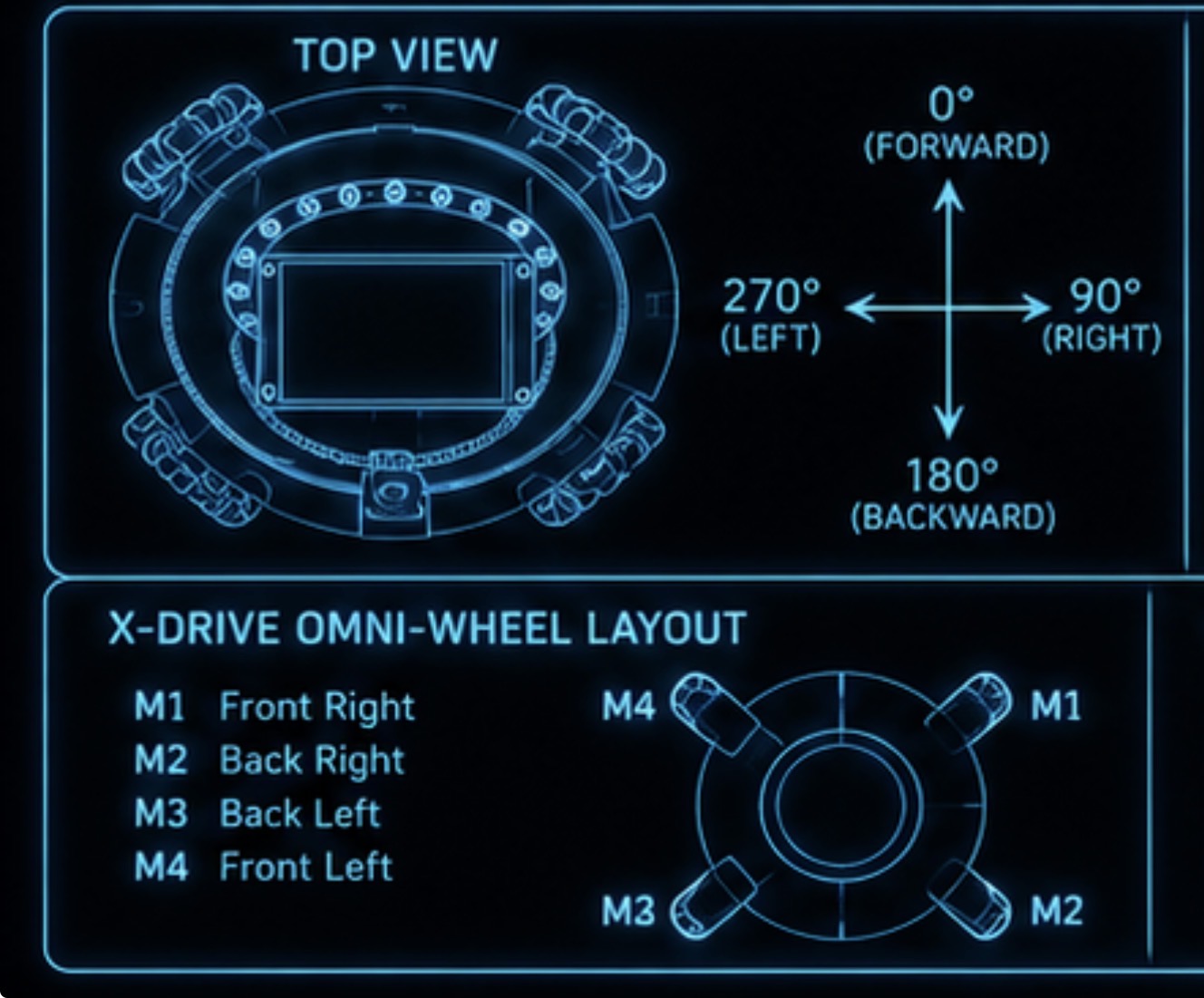
| Motor | Position | IN1 / pin1 | IN2 / pin2 |
|---|---|---|---|
| M1 | Front-right | GP11 | GP10 |
| M2 | Back-right | GP13 | GP12 |
| M3 | Back-left | GP15 | GP14 |
| M4 | Front-left | GP18 | GP19 |
All DRV8871 drivers share logic VCC (3.3 V from Pico) and GND. Motor power (6–12 V battery) connects to VM and PGND on each driver.
| BNO055 pin | Pico pin | settings.py |
|---|---|---|
| SDA | GP0 | IMU_SDA_PIN = 0 |
| SCL | GP1 | IMU_SCL_PIN = 1 |
| VIN | 3.3 V | IMU_FREQUENCY = 100000 |
| GND | GND | IMU_I2C_ID = 0 |
Uses hardware I²C peripheral 0 at 100 kHz. Detection is automatic: i2c.scan() checks both addresses (0x28 and 0x29).
| Signal | Sensor Pico | Drive Pico | settings.py |
|---|---|---|---|
| Data | TX pin | GP5 (RX) | RX_PIN = 5 |
| GND | GND | GND | — |
One data wire + shared GND. Both Picos must use UART_BAUD = 115200. Drive Pico uses UART peripheral 1 (GP5 is UART1 RX).
Motor Setup
Complete hardware wiring for the robot Pico, all four motors, the IMU, the sensor ring, the Nextion display, and the IR sensors. Use this page when building or debugging the robot.
| Pico pin | Connected to | Component pin | Purpose |
|---|---|---|---|
| GP0 | BNO055 IMU | SDA | I²C data line |
| GP1 | BNO055 IMU | SCL | I²C clock line |
| GP5 | Sensor-ring Pico | UART TX | Receives the calculated IR ball angle (UART1 RX) |
| GP10 | Motor 1 driver | M1 input B | Front-right motor direction / PWM |
| GP11 | Motor 1 driver | M1 input A | Front-right motor direction / PWM |
| GP12 | Motor 2 driver | M2 input B | Back-right motor direction / PWM |
| GP13 | Motor 2 driver | M2 input A | Back-right motor direction / PWM |
| GP14 | Motor 3 driver | M3 input B | Back-left motor direction / PWM |
| GP15 | Motor 3 driver | M3 input A | Back-left motor direction / PWM |
| GP16 | Nextion display | RX | Robot Pico transmits commands to the display (UART0 TX) |
| GP17 | Nextion display | TX | Robot Pico receives data from the display (UART0 RX) |
| GP18 | Motor 4 driver | M4 input A | Front-left motor direction / PWM |
| GP19 | Motor 4 driver | M4 input B | Front-left motor direction / PWM |
| GND | All devices | GND | Shared electrical reference |
Each motor uses two PWM signals from the robot Pico going to the two control inputs of that motor’s driver channel — never directly to the motor.
| Motor | Position | Pin A (IN1) | Pin B (IN2) | Code |
|---|---|---|---|---|
| M1 | Front-right | GP11 | GP10 | Motor(11, 10) |
| M2 | Back-right | GP13 | GP12 | Motor(13, 12) |
| M3 | Back-left | GP15 | GP14 | Motor(15, 14) |
| M4 | Front-left | GP18 | GP19 | Motor(18, 19) |
Motor direction logic
The Motor.run() method applies PWM to one pin and zero to the other:
| Requested speed | Pin A | Pin B | Result |
|---|---|---|---|
| Positive | PWM active | 0 | Motor turns in its calibrated forward direction |
| Negative | 0 | PWM active | Motor turns in the opposite direction |
| Zero | 0 | 0 | Motor coasts to a stop |
Motor position reference
            FRONT — 0°
     M4                    M1
 Front-left            Front-right
     M3                    M2
  Back-left             Back-right
            BACK — 180°
| BNO055 pin | Robot Pico pin | Purpose |
|---|---|---|
| SDA | GP0 | Sends and receives I²C data |
| SCL | GP1 | I²C clock signal |
| GND | GND | Common ground |
| VIN / VCC | Regulated supply | 3.3 V or 5 V depending on the specific breakout board — check the board label |
The code uses I2C(0, sda=Pin(0), scl=Pin(1), freq=100000) and automatically scans for
address 0x28 then 0x29. The program halts at startup
if neither address is found — check wiring first.
| Nextion pin | Robot Pico pin | Direction | Purpose |
|---|---|---|---|
| RX | GP16 | Pico → display | Receives commands from the robot |
| TX | GP17 | Display → Pico | Sends touch events or serial messages |
| GND | GND | Shared | Common electrical reference |
| VCC | Regulated display supply | Power | Check the display model for required voltage before connecting |
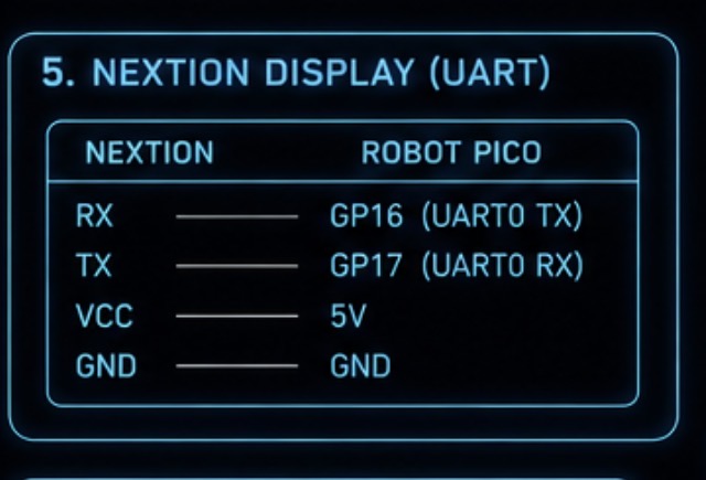
Remember: Pico GP16 (TX) → Nextion RX • Pico GP17 (RX) ← Nextion TX. The display should not be powered from the Pico’s 3.3 V pin — check its datasheet.
| Sensor-ring Pico | Robot Pico | Purpose |
|---|---|---|
| GP0 (UART0 TX) | GP5 (UART1 RX) | Sends the ball angle as text, e.g. 143
|
| GND | GND | Shared reference — required even if only one wire carries data |
| GP1 (UART0 RX) | Not connected | No return data is currently sent from the robot to the sensor ring |
The sensor ring transmits one integer angle followed by a newline character each loop. Both Picos must use baud rate 115200 or the data will be garbage.
Each sensor is wired as Pin.IN, Pin.PULL_UP.
A LOW signal means the ball is detected at that sensor’s angle.
| Sensor # | Angle | Sensor-ring Pico pin |
|---|---|---|
| 12 | 0° (front) | GP15 |
| 1 | 30° | GP14 |
| 2 | 60° | GP13 |
| 3 | 90° (right) | GP12 |
| 4 | 120° | GP11 |
| 5 | 150° | GP10 |
| 6 | 180° (back) | GP9 |
| 7 | 210° | GP8 |
| 8 | 240° | GP7 |
| 9 | 270° (left) | GP6 |
| 10 | 300° | GP5 |
| 11 | 330° | GP4 |
Each IR sensor needs three connections: signal/output → assigned GPIO, GND → GND, and power → the voltage appropriate for that IR sensor module.
| Link | UART | Baud | TX pin | RX pin |
|---|---|---|---|---|
| Sensor-ring Pico (outgoing) | UART0 | 115200 | GP0 | GP1 |
| Robot Pico receives sensor data | UART1 | 115200 | — | GP5 |
| Robot Pico ↔ Nextion display | UART0 | 9600 | GP16 | GP17 |
The two UART systems on the robot Pico are completely separate: GP5 receives ball angle data; GP16/GP17 communicate with the Nextion display.
All devices that exchange signals must share a common ground. Without it, UART, I²C, and PWM signals behave unpredictably even when the signal wires look correct.
| Device | Ground must connect to |
|---|---|
| Robot Pico | Main common ground |
| Sensor-ring Pico | Main common ground |
| BNO055 IMU | Main common ground |
| Nextion display | Main common ground |
| Motor driver logic | Main common ground |
| Voltage regulator | Main common ground |
| Battery negative | Main common ground |
⚠ Power wiring — confirm before connecting
The program files do not specify the following. Confirm these from the physical robot or component datasheets before connecting power:
- Battery voltage and chemistry
- Exact motor driver model and its power terminals (VM / PGND)
- Voltage regulator type and output rail
- Whether each Pico is powered from VSYS, VBUS, or an external supply
- Nextion display required supply voltage (check its model number)
- BNO055 breakout board power requirement (3.3 V or 5 V)
- Whether the sensor-ring Pico has its own regulator
Troubleshooting
Something not working? Start here. Each card describes the symptom, the most likely cause, and how to fix it.
🚨 Robot does not move at all / halts at startup
- The IMU was not found. The program calls
stop()and loops forever ifinitialise_imu()returnsNone. - Check GP0 (SDA) and GP1 (SCL) wiring to the BNO055. Swap them if needed.
- Check the BNO055 has 3.3 V power and a shared GND with the Pico.
- In the REPL:
from imu import initialise_imu; print(initialise_imu()). Should print aBNO055object.
🚨 Robot stops immediately after startup (fail-safe)
- The sensor ring is not sending data. Check UART wiring: sensor Pico TX → drive Pico GP5, plus shared GND.
- Make sure
UART_BAUDmatches on both Picos (must both be 115200). - In the REPL:
from sensor_ring import SensorRing; r = SensorRing(); import time; time.sleep_ms(500); print(r.read()). Should print a number, notNone.
⚠ Robot moves in the wrong direction
- Check motor wiring. Swap IN1/IN2 for any motor that spins backwards to reverse its direction.
- Verify
MOTOR_PINSorder: index 0 = front-right, 1 = back-right, 2 = back-left, 3 = front-left. - Do not change the signs in the mixing equations in
drive.py— fix the wiring instead.
⚠ Heading correction steers the wrong way
- Change
ROTATION_SIGN = 1toROTATION_SIGN = -1insettings.py. - If correction is too aggressive (robot jitters), reduce
HEADING_KP. - If the robot barely corrects, increase
HEADING_KP.
💡 Robot orbits but never pushes
- Increase
FRONT_WINDOW(e.g. 15 → 25). The ball angle must be within this window to trigger a push. - Check that the sensor ring has 0° = front. If 0° is rear, offset readings by 180 on the sensor-ring Pico.
💡 Robot pushes / orbits at the wrong speed
- Adjust
PUSH_POWERandORBIT_POWERinsettings.py. - The speed normaliser in
drive()will scale all four motors proportionally if any exceedsMAX_POWER. Increasing power pastMAX_POWERwill not actually make the robot faster.
🔍 ImportError when running main.py
- A file is missing or named incorrectly on the Pico. All five files must be present:
settings.py,drive.py,imu.py,sensor_ring.py,main.py. - Check for typos: file names are case-sensitive on the Pico’s filesystem.
Knowledge Check
Click each question to reveal the answer. Try to answer without peeking first!
What does a ball angle of 270° mean? ▶ Show answer
The ball is directly to the left of the robot. The angle system is 0° = front, 90° = right, 180° = behind, 270° = left (clockwise from front).
Why does the program halt if initialise_imu() returns None?
▶ Show answer
The IMU is required for heading hold. Without it the robot would spin
randomly after every collision. The program calls stop() and enters an
infinite loop, forcing you to fix the wiring before running.
What does ROTATION_SIGN = -1 do?
▶ Show answer
It reverses the heading-correction direction. If the robot turns the wrong way after a
collision, changing this to -1 in settings.py fixes it
without touching any logic code.
How does drive.py prevent one motor from exceeding MAX_POWER?
▶ Show answer
The drive() function finds the largest absolute speed value. If it exceeds
MAX_POWER, it computes a scale factor (MAX_POWER / largest) and
multiplies all four speeds by it. This keeps direction correct while
capping the output.
What does wrap_180(270) return, and why is that useful?
▶ Show answer
It returns −90. Converting 0–359 to −180–+180 makes
it easy to tell left (negative) from right (positive) and to compute the shortest
rotation to any target heading.
What happens if the sensor ring stops sending data for 600 ms? ▶ Show answer
sensor_ring.age() will return 600, which exceeds BALL_TIMEOUT = 500.
The condition sensor_ring.age() > BALL_TIMEOUT is true, so stop()
is called. The robot waits 10 ms and tries again next loop.
Why does main.py wait 3 seconds before doing anything?
▶ Show answer
time.sleep(3) gives the IMU time to power up and gives you time to set the
robot down and let go before the program reads target_heading. The heading
recorded at that moment is the direction the robot will always try to face.
Why do we use uart.any() before calling uart.read()?
▶ Show answer
uart.any() returns the number of bytes waiting. Calling uart.read()
when there is nothing returns None, which would cause a crash when we try to
append it to the buffer. Checking first is safer and slightly faster.
How does imu.py detect whether the BNO055 is at address 0x28 or 0x29?
▶ Show answer
It calls i2c.scan() which returns a list of all I²C addresses
found on the bus. It checks if 0x28 is in that list first, then
0x29. If neither is found, it returns None.
Which file do you edit to change the GPIO pin for the sensor ring RX, and what constant? ▶ Show answer
settings.py — change RX_PIN = 5 to the new pin number.
Never hardcode pin numbers directly in sensor_ring.py; always read from settings.
Robot Feature Poster
A printable A3 summary of all the main features of the soccer robot — handy to pin up at your workstation or take to the event. Click the Print / Save as PDF button inside the poster to print it.
- Click the Print / Save as PDF button in the top-right corner of the poster above.
- In the print dialog, set paper size to A3 and orientation to Portrait.
- Set margins to None so the dark background fills the page.
- Choose Save as PDF to keep a digital copy, or send straight to your printer.